Tutorial Introduction
Welcome to MeVisLab!
More than 20 years of experience and the continuous implementation of adaptations made MeVisLab one of the most powerful development platforms for medical image processing. Several applications and their prototypes are based on and could be realized because of MeVisLab, including software assistants for neuro-imaging, dynamic image analysis, surgery planning, and cardiovascular analysis.
MeVisLab is a development environment for rapid prototyping and product development of medical and industrial imaging applications. It includes a Software Development Kit (SDK) and an ApplicationBuilder for deploying your applications to end-customers.
In turn, the MeVisLab SDK consists of an Integrated Development Environment (IDE) for visual programming and the advanced text editor MATE for Python scripting, providing code completion, debugging, profiling and automated test development as well as execution.
You can re-use thousands of pre-defined Modules for image processing (2D up to 6D images) and visualization, combine them or even build your own.
A quick introduction on available modules and example networks will be given in the following tutorials.
Structure and usage of provided tutorials
This tutorial is a hands-on training. You will learn about basic mechanics and features of MeVisLab.
Starting with this introduction, we will be leading you through all relevant aspects of the user interface, commonly used functionalities and provide you with all the basic knowledge you need to build your own web applications.
Additional information is accessible through embedded links, forwarding you to a related glossary entry or tutorial and shortcuts, advice and hints will be highlighted as shown here.
The tutorials are divided into chapters by their topic and each chapter contains at least one example for you to try. You find them at the end of the tutorial or, also sorted by chapters, under the menu entry Examples. The examples under the designated menu entry are more suitable if you already have a little experience and rather search for inspiration than for explanations.
Starting MeVisLab for the first time
Right after installation of MeVisLab, you will find some new icons on your Desktop (if selected during setup).
![]()
Use the top middle icon to start the MeVisLab IDE. You can also start the integrated text editor MATE or the ToolRunner. For this tutorial, you will generally require the IDE.
MeVisLab IDE User Interface
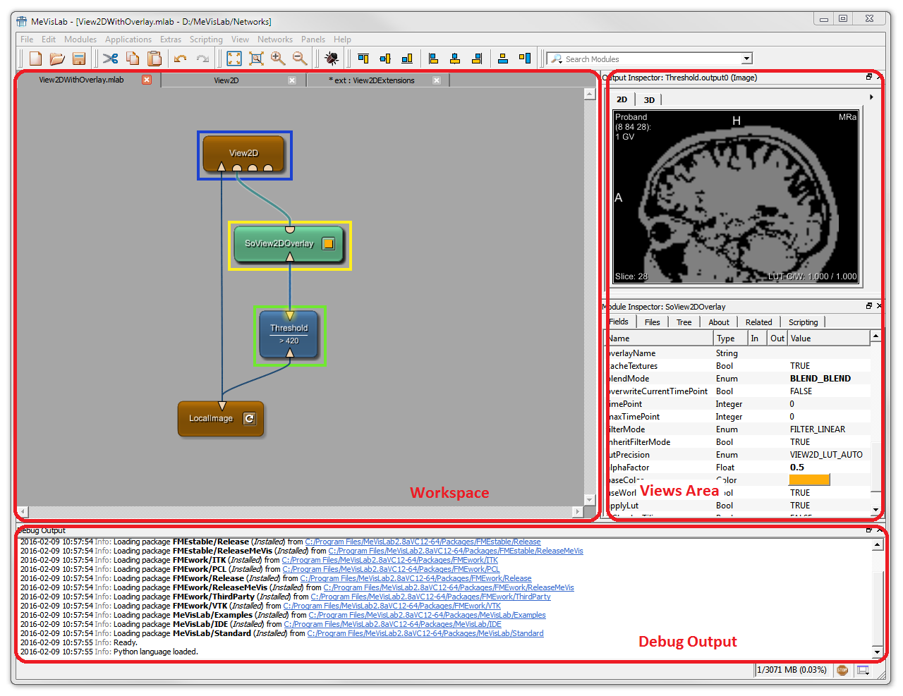
First, start the MeVisLab IDE. After the Welcome Screen, the standard user interface opens.
Workspace
By default, MeVisLab starts with an empty workspace.
This is where you will be developing and editing networks. Networks essentially form the base of all processing and visualization pipelines, so the workspace is, where the visual programming is done.
Views Area
The standard Views Area contains the Output Inspector and Module Inspector. With the help of the Output Inspector, you can visualize the modules output.
Debug Output
Debugging information can be found using the Debug Output.
The MeVisLab IDE and its layout are completely configurable. You can rearrange the items and add new views via [ Main Menu → View → Views ].
Filetypes used in, for and with MeVisLab
Extension | Description |
|---|---|
.mlab | Network file, includes all information about the networks modules, their settings, their connections, and module groups. Networks developed using the MeVisLab SDK are stored as .mlab files and can only be opened having a valid SDK license. |
.def | Module definition file, necessary for a module to be added to the common MeVisLab module database. May also include all MDL script parts (if they are not sourced out to the .script file). |
.script | MDL script file, typically includes the user interface definition of panels. See Chapter GUI Development for an example on GUI programming. |
.mlimage | MeVisLab internal image format for 6D images saved with all DICOM tags, lossless compression, and in all data types. |
.mhelp | File with descriptions of all fields and possible use-cases of a module, edit- and creatable by using MATE. See Help files for details. |
.py | Python file, used for scripting in macro modules. See Python scripting for an example on macro programming. |
.dcm | DCM part of the imported DICOM file, see Importing DICOM Data. |
Module types
They provide the functionalities to process, display and interact with images.
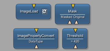
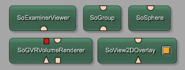
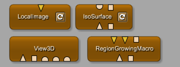
The three existing module types (ML, Open Inventor and macro module) can be distinguished by their colors:
Type | Appearance | Characteristics |
|---|---|---|
| ML module (blue) | Page-based, demand-driven processing of voxels. | |
| Open Inventor module (green) | Visual scene graphs (3D). Usually starting with So (for Scene object) as a naming convention. | |
| Macro module (brown) | Combination of other module types, allowing the implementation of hierarchies and scripted interaction. |
Invalid modules
If a module is invalid, it is displayed in bright red. This might happen if the module itself is not available for your system.
Appearance | Explanation |
|---|---|
| Invalid module | |
| Macro containing an invalid module |
As you can see, the number of warning and error messages that are being printed to the debug console are listed in the upper right corner of the module. This is intentional, as it enables the developer to quickly find the module causing the errors.
Informational messages are indicated in a similar matter on the same spot, but in a subtle grey color.
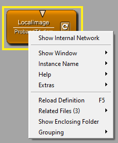
Module interactions through the Context Menu
Each module has a context menu, providing the following options:
- Show Internal Network: Macro modules provide an entry to open the internal network. You can see what happens inside a macro module. The internal network may also contain other macro modules.
- Show Window: If a module does not provide an User Interface, you will see the automatic panel, showing the module’s name. Modules may additionally have one or more windows which can be opened. You can also open the Scripting Console of a module to integrate Python.
- Instance Name: You can edit or copy the instance name. Renaming can be useful if the same module appears more than once in one network and/or if you want to access and distinguish the modules in your Python script.
- Help: The menu entry Help provides access to the Module Help pages and to an example network where the module is used. This example network often helps to understand which additional modules can be added to create your desired effect.
- Extras: Automated tests written for the specific module can be executed here. You can also run this module in a separate process.
- Reload Definition: In case you are currently working on a module, you may need to reload the definition so that your changes are applied on the module (for example attached Python scripts).
- Related Files: Related files allows a quick access to the modules *.script or *.py files. The files are automatically opened in MATE for editing.
- Show Enclosing Folder: This entry opens the directory where your module is stored.
- Grouping: Multiple modules can be clustered and the groups can be named. This adds clarity to the structure of your network. In addition to that, grouped modules can be converted to local- or global macro modules easily.
Input and Output Connectors
As the creation of a network requires connected modules, each module has input and output connectors, located on their top and bottom side. Data is transmitted from the output connector on the top side of one module to the input connector on another module’s bottom side.
Once again, three types can be distinguished:
Appearance | Shape | Definition |
|---|---|---|
| triangle | ML images | |
| half-circle | Inventor scene | |
| square | Base objects: Pointers to data structures |
Some modules even contain hidden connectors in addition to the ones displayed on the module’s surface. Click on the workspace and press SPACE to see the hidden connectors as well as the internal networks of each module. You can now also use the hidden connectors for building connections.
For more information about connectors and different types of connections click
here
.
If you want to know more about establishing, interrupting, moving and replacing connections, have a look at
this.
Parameter Connections
Besides through a module’s input and output connectors, connections can also be established between parameters in the module’s panel.
Macro modules
Adding modules to your workspace
There are several ways to add a module to your current network:
- via the menu bar entry [ Modules ].
- via [ Quick Search ].
- via the View Module Search.
- via the View Module Browser.
- via copy and paste from another network.
- by scripting, see the Scripting Reference
Both the menu entry[
Modules
] and the Module Browser display all available modules. The modules are sorted hierarchically by topic and name, as defined in the file Genre.def.
Therefore, both places are a good starting point when in need of a specific function, like an ImageLoad module.
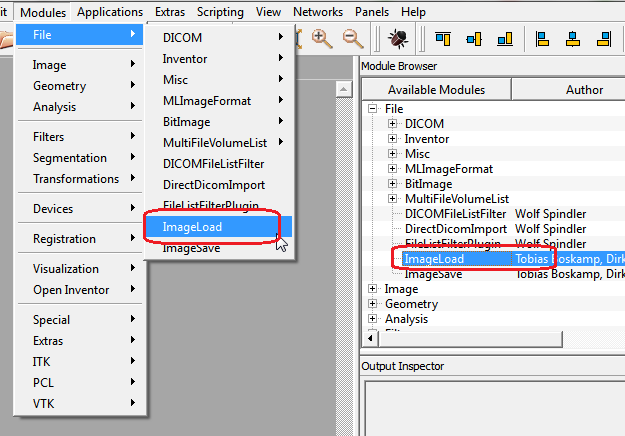
The advantage of the Module Browser is that you can right-click

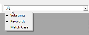
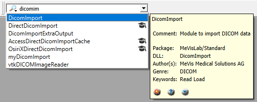
Usually the quickest way to add modules to a network is the quick search in the menu bar. It offers you the possibility to search for modules by module name. By default, the search will also be extended to keywords and substrings and is case-insensitive. To change these settings, click the magnifier button for the search options.
Use the ↑ ArrowUp and ↓ ArrowDown keys on your keyboard to move to one of the listed modules. The module’s decription will appear next to it, allowing you to decide if this is the right module for your use-case.
Abbreviations
| Abbreviation | Meaning |
|---|---|
| CSO | Contour Segmented Object |
| WEM | Winged Edge Mesh |
| GVR | Giga Voxel Renderer |
Components of MeVisLab
| Component | Description |
|---|---|
| MeVisLab | MeVisLab consists of the MeVisLab SDK and the MeVisLab ApplicationBuilder. |
| MeVisLab SDK | The MeVisLab Software Development Kit (SDK) is the MeVisLab IDE including the text editor MATE and any tools integrated for debugging, testing and profiling. |
| MeVisLab ApplicationBuilder | The MeVisLab ApplicationBuilder allows you to generate installable executables from your developed networks and applications. These executables can be delivered to customers. |
| MeVisLab IDE | The MeVisLab Integrated Development Environment (IDE) is your starting point whenever you are working with MeVisLab. It provides a programming interface and an advanced text editor. |
| MeVisLab MATE | The Advanced Text Editor (MATE) is an integrated text editor for Python and MDL development in MeVisLab. It provides auto-completion and syntax highlighting, as well as debugging functionalities. |
| MDL | The MeVisLab Definition Language (MDL) is the language for developing basic User Interfaces for networks and modules in MeVisLab. |
MeVisLab Terminology and Concepts
| Term | Description |
|---|---|
| Module | A module is a single instance providing encapsulated functionalities for a specific purpose. MeVisLab provides thousands of such pre-defined modules and you can develop your own modules for extending functionalities. modules provide inputs and outputs for connections in a network and/or one or more panels for interacting. |
| Panel | A panel is a User Interface providing possibilities to interact with MeVisLab. |
| Field | Parameters of modules are called fields. Several different types of fields are available such as numbers, text, trigger buttons, etc. Publicly accessible fields can be modified in the Module Inspector or Panel of the selected module. |
| Macro module | Macro modules encapsulate networks including input and output into a single module. In order to see whats inside a macro module, you can open the Context Menu via Right-Click and select [ Show Internal Network ]. You can choose to create local macros and global macros. |
| Local macro (module) | Local macros are only available in your currently opened network. You cannot use the Module Search in MeVisLab to find local macros. |
| Global macro (module) | Global macros are integrated into MeVisLab and can be used in any future networks. They are available in module search. |
| Network | A network contains at least two connected modules. |
| Example network | Each module provides an example network to see how it can be used. Right-Click on the module and select Help > Show Example Network |
| Output Inspector | The Output Inspector is a quick preview of the output of a specific module. The output can be an image or any other user defined output format. |
| Module Inspector | The Module Inspector shows publicly available properties of the selected module and their current values. Changes made in the Module Inspector are applied on the fly. |
| Workspace | The workspace is the area where you can add and connect modules. Multiple networks are organized in separate tabs. |
| Views Area | The right side of the MeVisLab IDE provides a space to add several predefined panels like Output- and Module inspectors. |
| Debug Output | The Debug Output shows debugging messages of your modules and the MeVisLab IDE. |
| Open Inventor | Open Inventor modules process and render 3D scene objects and enable image interactions. |
| Scene Object | Scenes are tree graphs of objects used in Open Inventor. A single object is called Node or Scene Object. This can be a shape, transformation, attribute or any other module of the So*-family. |
| Lookup Table (LUT) | A lookup table (LUT) maps input values to other static values. In MeVisLab they can be used, for example, to translate grey values from an input image to colors used for rendering. |
| Package | Macro modules and projects are stored in packages. They are a way of organizing different projects within MeVisLab. |


